
In modern coil processing, manufacturers increasingly need to produce non-rectangular metal blanks that match the geometry of downstream stamping and forming operations. Trapezoidal blanks are used in applications where angled edges help accommodate component designs, optimize material layouts, or reduce unnecessary trimming. An Oscillating Shear Machine provides a flexible way to produce these shapes from continuously fed metal strips. However, selecting the appropriate oscillating angle involves more than changing the cutting direction. It requires coordination between blank geometry, material properties, cutting accuracy, and production speed.
The oscillating angle determines how the cutting tool moves relative to the material feed direction and influences the resulting cut geometry. By adjusting the cutting setup, manufacturers can produce angled edges instead of relying exclusively on perpendicular cuts. This flexibility is valuable when processing trapezoidal blanks for automotive panels, appliance components, and other formed sheet metal parts. The required angle should be established from the finished blank drawing, including its upper and lower edge dimensions, side-edge geometry, and dimensional tolerances. Because the machine's oscillating angle is a mechanical process parameter, it should not automatically be treated as identical to the finished blank's geometric angle. The relationship must be verified against the selected tool design and cutting configuration.
Cutting accuracy depends on the relationship between the programmed cutting geometry and the actual movement of the sheet and shear mechanism. In continuous production, the cutting tool must synchronize with the moving strip to create the intended profile. An unsuitable setup or inconsistent material feeding can contribute to dimensional variation, uneven edges, or deviations from the specified blank geometry. Other important factors include material thickness, strip flatness, blade clearance, tool condition, and feed measurement accuracy. For manufacturers producing high-volume trapezoidal blanks, these variables should be evaluated together rather than attributing every dimensional error to the oscillating angle. Trial cutting, sample measurement, and repeatability checks help establish suitable operating parameters before full-scale production begins.
Material utilization is another important consideration when selecting an oscillating shear angle. Rectangular cutting may leave unnecessary scrap when the required component has angled edges or a tapered profile. Producing trapezoidal blanks can provide a better match between the incoming strip and the intended part geometry, particularly when the cutting pattern is designed around the dimensions of the finished component. However, a larger oscillating angle does not necessarily produce less waste. The result depends on coil width, blank dimensions, part layout, edge allowances, and the arrangement of successive cuts. Manufacturers should compare alternative blank geometries and calculate scrap rates using actual production layouts. This approach helps determine whether an adjusted cutting angle can deliver measurable material savings without compromising downstream forming requirements.
High-speed operation introduces additional considerations for continuous shearing. The cutting mechanism must coordinate its motion with the moving material while maintaining the required cut geometry. A production setup that works well at a lower speed may require further validation before operating at the target line speed, especially when material thickness, strength, or blank dimensions change. Manufacturers should therefore evaluate cutting accuracy, edge quality, feed stability, and stacking performance together when establishing production parameters.
SUMIKURA Co., Ltd. offers oscillated shear lines with different operating configurations. According to its product information, one configuration supports material widths up to 2,500 mm, thicknesses from 0.2 to 4.0 mm, and oscillating angles from 0° to 35°. It supports stop and rotary oscillating shear modes and lists HSS, CRS, HRS, and aluminum among its compatible materials. A separate rotary oscillating configuration handles widths from 400 to 1,850 mm, lengths from 500 to 4,000 mm, thicknesses from 0.4 to 3.0 mm, and oscillating angles from 0° to 32°. Both configurations list a maximum line speed of 80 m/min. These specifications describe different equipment options, so the appropriate model should be selected according to the actual production requirements rather than assuming that every parameter applies to every machine.
The appropriate oscillating shear setup also depends on the material being processed. High-strength steel, cold-rolled steel, hot-rolled steel, and aluminum differ in strength, hardness, ductility, and surface characteristics. These differences affect cutting forces, edge formation, and the risk of burrs or deformation. Material thickness and grade should therefore be confirmed before the cutting angle and operating conditions are finalized. Blade clearance and tool condition also require attention because an unsuitable clearance or worn cutting edge can reduce edge quality even when the angle is correctly set. For applications with strict dimensional or surface requirements, manufacturers should validate the complete cutting process using the actual material grade and thickness.
The performance of an Oscillating Shear Machine depends not only on the cutting unit but also on how it integrates with the rest of the production line. Upstream leveling helps provide consistent strip flatness, while accurate feeding and measurement support dimensional control. Downstream conveying and stacking systems must handle the resulting blanks without damaging their surfaces or disturbing their arrangement. SUMIKURA's oscillated shear tool information describes rectangular and trapezoidal cutting applications and shows sheet transfer through telescopic and magnetic conveyor systems toward stacking. When planning a new line or upgrading existing equipment, manufacturers should evaluate the cutting tool, material handling, automation requirements, and downstream process as one coordinated system.
Before choosing an oscillating shear configuration, manufacturers should confirm the finished blank drawing, required edge geometry, dimensional tolerances, material grade, thickness, and coil width. The next step is to establish the cutting setup and determine whether the required production rate is compatible with the selected machine configuration. Trial production should then be used to inspect blank dimensions, edge quality, scrap generation, and stacking performance. If the blanks will enter a stamping or forming process, their geometry should also be checked against the requirements of the downstream tooling. These checks help prevent a seemingly suitable cutting angle from creating problems later in the production workflow.

Your cutting line specialists!
 Factory in Japan

ADDRESS
487-3, Sanshincho, Chuoku, Hamamatsu, Shizuoka, Japan
 Japan local market : +81 53-425-5331
Factory in China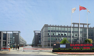
ADDRESS
265 Yixian Road, Deqing, Zhejiang, China
Overseas market : +86 572-883-2016



